







• Finding Feature Information, on page 1
• Prerequisites for Switch Stacks, on page 1
• Restrictions for Switch Stacks, on page 1
• Information About Switch Stacks, on page 2
• How to Configure a Switch Stack, on page 8
• Configuration Examples for Switch Stacks, on page 10
• Feature History and Information for Switch Stacks, on page 18
Your software release may not support all the features documented in this module. For the latest caveats and
feature information, see Bug Search Tool and the release notes for your platform and software release. To
find information about the features documented in this module, and to see a list of the releases in which each
feature is supported, see the feature information table at the end of this module.
Use Cisco Feature Navigator to find information about platform support and Cisco software image support.
To access Cisco Feature Navigator, go to http://www.cisco.com/go/cfn. An account on Cisco.com is not
required.
All the switches in the switch stack need to be running the same license level as the active switch. For
information about license levels, see the System Management section of this guide.
All switches in the switch stack need to be running compatible software versions.
The following are restrictions for your switch stack configuration:
• A switch stack can have up to eight stacking-capable switches connected through their StackWise-480
ports.
• Only homogenous stacking is supported, that is, a stack of Cisco Catalyst 9300 Series Switchesavec
only Cisco Catalyst 9300 Series Switches as stack members.
• You cannot have a switch stack containing a mix of different license levels.
A switch stack can have up to eight stacking-capable switches connected through their StackWise-480 ports.
The stack members work together as a unified system. Layer 2 and Layer 3 protocols present the entire switch
stack as a single entity to the network.
A switch stack always has one active switch and one standby switch. If the active switch becomes unavailable,
the standby switch assumes the role of the active switch, and continues to the keep the stack operational.
The active switch controlsthe operation of the switch stack, and isthe single point ofstack-wide management.
From the active switch, you configure:
• System-level (global) voir aussi: features that apply to all stack members
• Interface-level features for each stack member
The active switch contains the saved and running configuration files for the switch stack. The configuration
files include the system-level settings for the switch stack and the interface-level settings for each stack
member. Each stack member has a current copy of these files for back-up purposes.
A standalone device is a device stack with one stack member that also operates as the active switch. You can
connect one standalone device to another to create a device stack containing two stack members, with one of
them as the active switch. You can connect standalone devices to an existing device stack to increase the stack
membership.
Hello messages are sent and received by all stack members.
• If a stack member does not respond, that member is removed from the stack.
• If the standby device does not respond, a new standby device is elected.
• If the active device does not respond, the standby device becomes the active device.
In addition, keepalive messages are sent and received between the active and standby devicees.
• If the standby device does not respond, a new standby device is elected.
• If the active device does not respond, the standby device becomes the active device.
If you replace a stack member with an identical model, the new switch functions with exactly the same
configuration as the replaced switch, assuming that the new switch (referred to as the provisioned switch) is
using the same member number as the replaced switch.
The operation of the switch stack continues uninterrupted during membership changes unless you remove the
active switch or you add powered-on standalone switches or switch stacks.
• Adding powered-on switches (merging) causes all switches to reload and elect a new active switch from
among themselves. The newly elected active switch retains its role and configuration. All other switches
retain their stack member numbers and use the stack configuration of the newly elected active switch.
• Removing powered-on stack members causes the switch stack to divide (partition) into two or more
switch stacks, each with the same configuration. This can cause:
• An IP address conflict in your network. If you want the switch stacks to remain separate, change
the IP address or addresses of the newly created switch stacks.
• A MAC address conflict between two members in the stack. You can use the stack-mac update
force command to resolve the conflict.
If a newly created switch stack does not have an active switch or standby switch, the switch stack will reload
and elect a new active switch.
Make sure that you power off the switches that you add to or remove from the switch stack.
After adding or removing stack members, make sure that the switch stack is operating at full bandwidth (480
Gbps). Press the Mode button on a stack member until the Stack mode LED is on. The last two right port
LEDs on all switches in the stack should be green. Depending on the switch model, the last two right ports
are 10-Gigabit Ethernet ports or small form-factor pluggable (SFP) module ports (10/100/1000 ports). If one
or both of these LEDs are not green on any of the switches, the stack is not operating at full bandwidth.
If you remove powered-on members but do not want to partition the stack:
• Power off the switches in the newly created switch stacks.
• Reconnect them to the original switch stack through their stack ports.
• Power on the switches.
For cabling and power considerations that affect switch stacks, see the Cisco Catalyst 9300 Series Switches
Hardware Installation Guide .
The stack member number (1 to 8) identifies each member in the switch stack. The member number also
determines the interface-level configuration that a stack member uses. You can display the stack member
number by using the show switch EXEC command.
A new, out-of-the-box switch (one that has not joined a switch stack or has not been manually assigned a
stack member number)ships with a defaultstack member number of 1. When it joins a switch stack, its default
stack member number changes to the lowest available member number in the stack.
Stack members in the same switch stack cannot have the same stack member number. Every stack member,
including a standalone switch, retains its member number until you manually change the number or unless
the number is already being used by another member in the stack.
• If you manually change the stack member number by using the switch current-stack-member-number
renumber new-stack-member-number EXEC command, the new number goesinto effect after thatstack
member resets (or after you use the reload slot stack-member-number privileged EXEC command) and
only if that number is not already assigned to any other members in the stack. Another way to change
the stack member number is by changing the SWITCH_NUMBER environment variable.
If the number is being used by another member in the stack, the switch selectsthe lowest available number
in the stack.
If you manually change the number of a stack member and no interface-level configuration is associated
with that new member number, that stack member resets to its default configuration.
You cannot use the switchcurrent-stack-member-number renumber new-stack-member-number EXEC
command on a provisioned switch. If you do, the command is rejected.
• If you move a stack member to a different switch stack, the stack member retains its number only if the
number is not being used by another member in the stack. If it is being used, the switch selects the lowest
available number in the stack.
• If you merge switch stacks, the switch that join the switch stack of a new active switch select the lowest
available numbers in the stack.
As described in the hardware installation guide, you can use the switch port LEDs in Stack mode to visually
determine the stack member number of each stack member.
You can enter the Stack mode on any of these switches by pressing the mode button. Based on the switch
number configured on each switch, the corresponding port LED will be blinking green. For instance, if the
switch number configured on a particular switch is three, then the port LED-3 will be blinking green when
the mode button is set to stack.
A higher priority value for a stack member increases the probability of it being elected active switch and
retaining its stack member number. The priority value can be 1 to 15. The default priority value is 1. You can
display the stack member priority value by using the show switch EXEC command.
We recommend assigning the highest priority value to the device that you prefer to be the active switch. This
ensures that the device is reelected as the active switch if a reelection occurs.
To change the priority value for a stack member, use the switch stack-member-number priority new
priority-value EXEC command. For more information, see the “Setting the Stack Member Priority Value”
section.
The new priority value takes effect immediately but does not affect the current active switch. The new priority
value helps determine which stack member is elected as the new active switch when the current active switch
or the switch stack resets.
A switch stack is identified in the network by its bridge ID and, if it is operating as a Layer 3 device, its router
MAC address. The bridge ID and router MAC address are determined by the MAC address of the active
switch.
If the active switch changes, the MAC address of the new active switch determines the new bridge ID and
router MAC address.
If the entire switch stack reloads, the switch stack uses the MAC address of the active switch.
You can use the persistent MAC address feature to set a time delay before the stack MAC address changes.
During this time period, if the previous active switch rejoins the stack, the stack continues to use its MAC
address as the stack MAC address, even if the switch is now a stack member and not an active switch. If the
previous active switch does not rejoin the stack during this period, the switch stack takes the MAC address
of the new active switch as the stack MAC address. By default, the stack MAC address will be the MAC
address of the first active switch, even if a new active switch takes over.
You can also configure stack MAC persistency so that the stack MAC address never changes to the new active
switch MAC address, by using the stack-mac persistent timer 0 command.
All stack members are eligible to be the active switch or the standby switch. If the active switch becomes
unavailable, the standby switch becomes the active switch.
An active switch retains its role unless one of these events occurs:
• The switch stack is reset.
• The active switch is removed from the switch stack.
• The active switch is reset or powered off.
• The active switch fails.
• The switch stack membership is increased by adding powered-on standalone switches or switch stacks.
The active switch is elected or reelected based on one of these factors and in the order listed:
1. The switch that is currently the active switch.
2. The switch with the highest stack member priority value.
We recommend assigning the highest priority value to the switch that you prefer to be the active switch. This
ensures that the switch is reelected as active switch if a reelection occurs.
Note
3. The switch with the shortest start-up time.
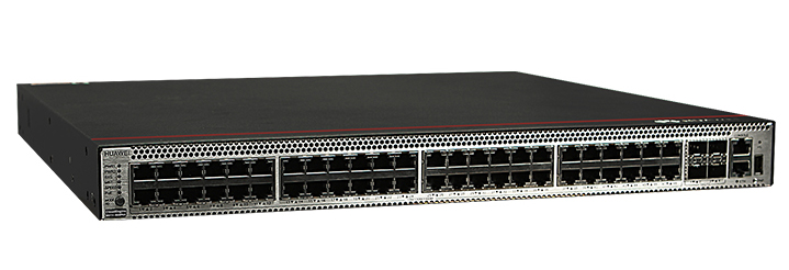
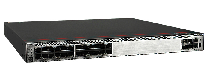
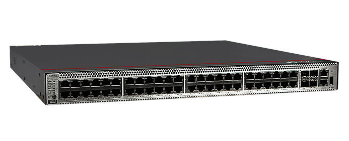
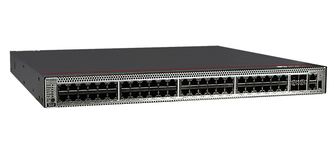
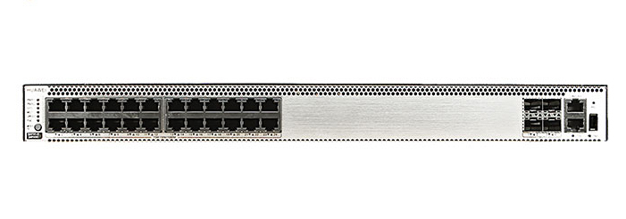
Cisco Catalyst 9300 Series Switches
For Cisco product list and quote, please visit: https://www.hi-network.com/categories/cisco or contact us at www.hi-network.com (Email: [email protected])
 Tags chauds:
Commutateurs CISCO
hot products