Inscrivez-vous maintenant pour un meilleur devis personnalisé!

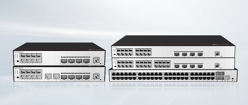
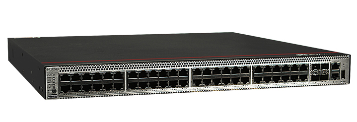
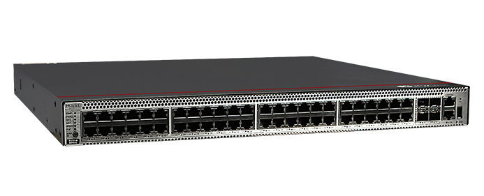


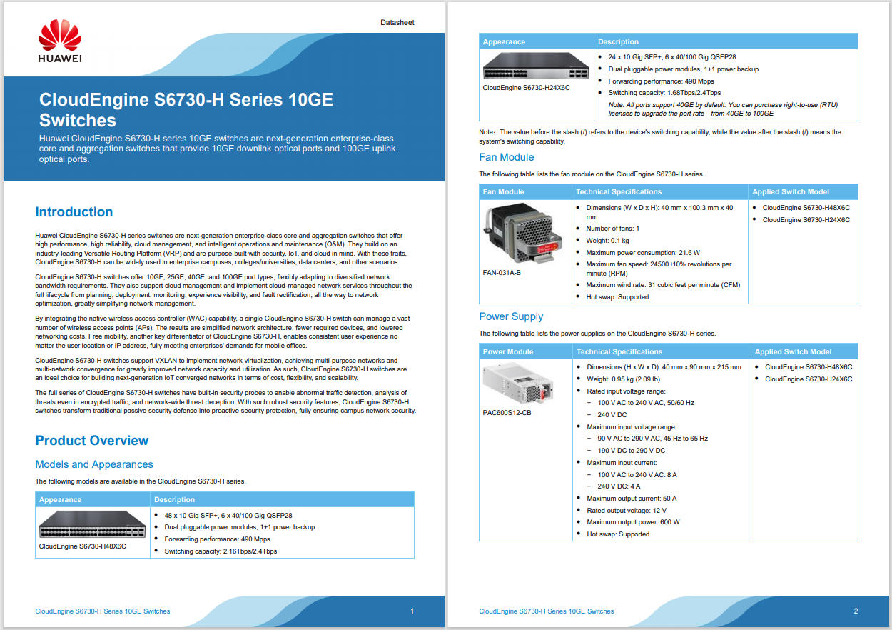

The CloudEngine S5731‑S48P4X is a high‑performance, PoE‑enabled gigabit access switch designed for campus and aggregation deployments............. It belongs to Huawei’s CloudEngine S5731‑S series, built on the versatile VRP platform and delivering robust Layer 2/Layer 3 functions, IPv6 readiness, intelligent stack capabilities, and efficient O&M solutions.
This model combines PoE+ support, a high switching capacity, redundant power options, and advanced security features, making it ideal for enterprise, MAN, and data‑center access usage.
For more datasheets, please go to the Download tab on each product details page, or search in the Datasheet Download Center.
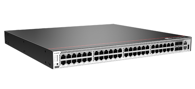
▪Ports: 48 × 10/100/1000BASE‑T PoE+ ports, 4 × 10GE SFP+ uplink ports
▪Forwarding performance: 125 Mpps
▪Switching capacity: 176 Gbps (device), 672 Gbps (stack)
▪Power modules: Two hot‑swappable (PAC600 AC/1000 W DC PoE modules) supporting up to 1000 W PoE each
▪Dimensions: 442 mm × 420 mm × 43.6 mm (1 U)
▪Weight: ~8.6 kg (typical with power modules)
The S5731‑S48P4X is based on high-performance switching hardware and Huawei's VRP OS. It supports iStack (stacking up to nine units), redundant power supply, hot-swap modules, zero‑touch provisioning, USB-based batch upgrades, SNMP/v2c/v3, CLI, web-UI, and RMON for comprehensive network management.
Supports VLAN, QinQ, MAC/IP-based VLAN, GVRP, LLDP/LLDP‑MED; Layer 3 includes static, RIPng, OSPF, IS-IS, BGP, VRRP, MPLS, iStack-aware routing and IPv4/IPv6 dual-stack with tunneling.
Defends against DoS attacks (SYN flood, Smurf), ARP spoofing, bogus DHCP servers, MAC address spoofing. Implements DHCP snooping, IP/MAC authentication, 802.1X, Portal Auth, ACLs, QoS traffic policing and shaping.
SEP and ERPS: ring protection, STP/RSTP/MST MSTP, Smart Link, Ethernet OAM, hot‑swappable fans & power, iStack redundancy—all ensure sub‑50 ms failover for resilient campus and MAN environments.
Supports IPv4/IPv6 dual‑stack, RIPng, manual/6‑to‑4/ISATAP tunnels for seamless migration and deployment in IPv6-capable networks.
PoE+ provides continuous power during reboots, supporting typical IEEE 802.3at devices. With two modules, delivers up to 2000 W total, enough for high-power applications.
Features telemetry via CampusInsight, enhanced Media Delivery Index (eMDI), encrypted communication analytics (ECA), and Python-based OPS scripting for intelligent network operations.
▪ Campus access layer: high-performance 48‑port PoE edge for IP phones/Wi-Fi APs
▪ Aggregation in SMB/MAN: IPv6-ready L3 routing with MPLS and VPN capabilities
▪ Small data center access: stacking capacity and redundancy ensure scalability and reliability
▪ modèle designation: S5731‑S48P4X (48 PoE+ ports, 4 × 10GE, no modules)
▪ Power modules: PAC600 AC or PDC1000 DC PoE (hot‑swappable racks)
Meets key safety standards: IEC 60950‑1, EN 60950‑1, UL 60950‑1, CSA C22.2, AS/NZS 60950.1
The Huawei CloudEngine S5731‑S48P4X is a powerful, feature-packed PoE+ gigabit access switch. With robust hardware, flexible power, advanced L2/L3 networking, security, zero‑touch O&M, and stacking capability, it’s an ideal solution for campus, aggregation, and data‑center access scenarios requiring scalability, reliability, and intelligent network management.
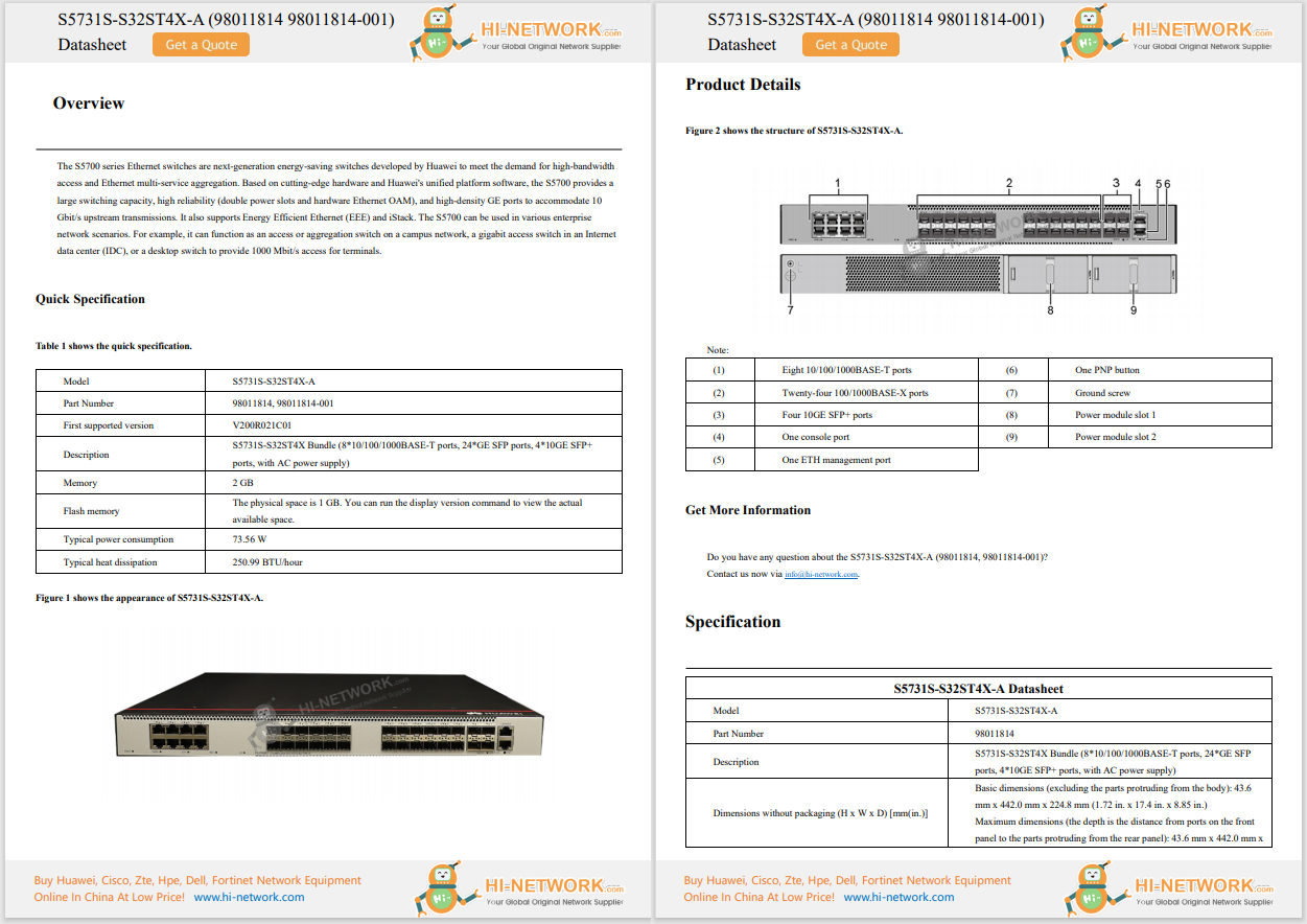
Huawei CloudEngine Switch S5731-S48P4X (02353AJH/-001/-003)
Huawei All Les séries Switches New and Used
For Huawei product list and quote, please visit: https://www.hi-network.com/categories/huawei or contact us at www.hi-network.com Re88pl99ace1 (Email: [email protected])
Table 4-1344 lists the mapping between the S5731-S48P4X chassis and software versions.
Series | Model | Version du logiciel |
|---|---|---|
S5731-S | S5731-S48P4X | 02353AJH: V200R019C00 and later versions 02353AJH-001: V200R020C10 and later versions 02353AJH-003: V200R021C10SPC600 and later versions (If V200R021C10SPC500 is used, install V200R021HP0121 or a later patch.) |
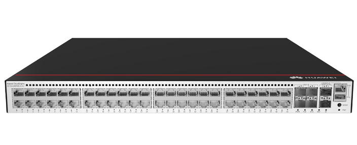
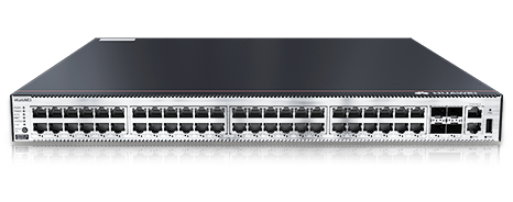
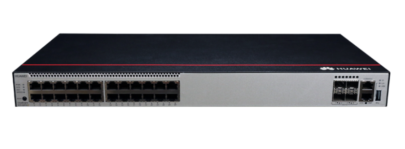
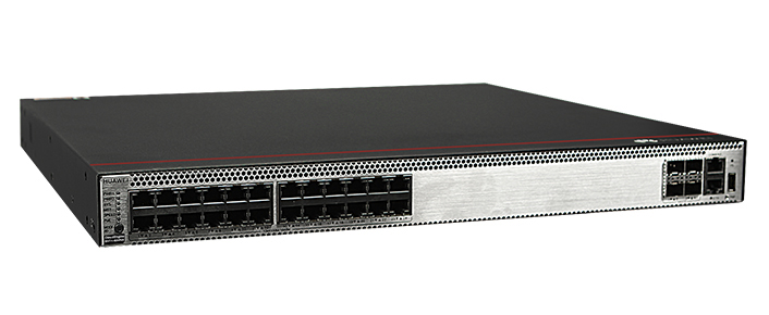
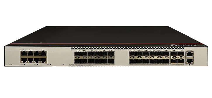
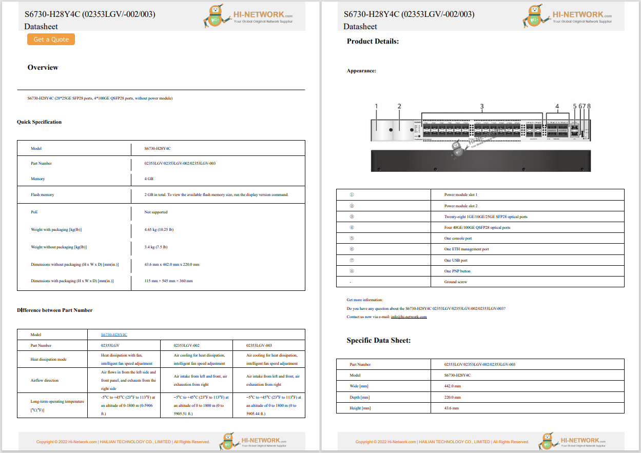
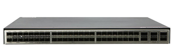
Figure 4-529 S5731-S48P4X (02353AJH) appearance
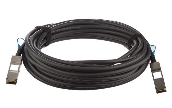
1 | Quarante-huit ports PoE+ 10/100/1000BASE-T | 2 | Quatre ports 10GE SFP+ Modules et câbles applicables:
|
3 | Un port de console | 4 | Un port de gestion l’epf |
5 | Un port USB | 6 | Un bouton PNP NOTICE:To restore the factory settings and reset the switch, hold down the button for at least 6 seconds. To reset the switch, press the button. Resetting the switch will cause service interruption. Exercise caution when you press the PNP button. |
7 | Vis de terre Remarque:It is used with a ground cable. | 8 | Fente de module de Fan 1 Remarque:Applicable fan module: FAN-023A-B (Fan Box (B, Fan Panel Side Exhaust)) |
9 | Fente de module de Fan 2 Remarque:Applicable fan module: FAN-023A-B (Fan Box (B, Fan Panel Side Exhaust)) | 10 | Emplacement de module de puissance 1 Remarque:Applicable power module:
|
11 | Emplacement de module de puissance 2 Remarque:Applicable power module:
| - | - |
10/100/1000BASE-T port
A 10/100/1000BASE-T Ethernet electrical port sends and receives service data at 10/100/1000 Mbit/s, and must use an Ethernet cable. Table 4-1345 describes the attributes of a 10/100/1000BASE-T Ethernet electrical port.Table 4-1345 Attributes of a 10/100/1000BASE-T Ethernet electrical port
Attribute | Description |
|---|---|
Type de connecteur | RJ45 |
Standards compliance | IEEE802.3, IEEE802.3u, IEEE802.3ab |
Mode fonctionnant | 10/100/1000 Mbit/s auto-sensing |
Maximum transmission distance | 100 m |
10GE SFP+ optical port
A 10GE SFP+ Ethernet optical port supports auto-sensing to 1000 Mbit/s. It sends and receives service data at 1000 Mbit/s or 10 Gbit/s. Table 4-1346 describes the attributes of a 10GE SFP+ Ethernet optical port.Table 4-1346 Attributes of a 10GE SFP+ port
Attribute | Description |
|---|---|
Type de connecteur | LC/PC |
Optical port attributes | Depend on the optical module used |
Standards compliance | IEEE802.3ae |
Mode fonctionnant | GE/10GE auto-sensing |
Port Console
The console port is connected to a console for on-site configuration. The port must use a console cable. The console port is used when a switch is powered on for the first time. For details about the attributes of a console port, see Table 4-1347.Table 4-1347 Attributes of a console port
Attribute | Description |
|---|---|
Type de connecteur | RJ45 |
Standards compliance | RS-232 |
Mode fonctionnant | Duplex Universal Asynchronous Receiver/Transmitter (UART) |
Baud rate | 9600 bit/s, 19200 bit/s, 38400 bit/s, 57600 bit/s, or 115200 bit/s Default value: 9600 bit/s |
Port de gestion ETH
You can connect a switch to a configuration terminal or network management workstation through the ETH management port to configure the switch locally or remotely. The port must use an Ethernet cable. You can choose to download the software package through the ETH management port in the BootLoad menu. File transfer through the ETH management port is faster than transfer through the console port. Table 4-1348 describes the attributes of an ETH management port.Table 4-1348 Attributes of an ETH management port
Attribute | Description |
|---|---|
Type de connecteur | RJ45 |
Standards compliance | IEEE802.3 |
Working Mode | 10/100 Mbit/s auto-sensing |
Maximum transmission distance | 100 m |
In V200R012C00 and later versions, you can log in to the switch that contains the ETH management port for the first time through the ETH port. For details, see "First Login to a Switch" in the Configuration Guide - Basic Configuration. If you have logged in to the switch for the first time by pressing and holding the MODE MODE button for 6 seconds or longer and saved the configuration, the default configuration on the ETH port will be cleared. In this case, you cannot log in to the switch for the first time through the ETH port. You are advised to log in to the switch for the first time through the ETH port.
Port USB
The USB port can have a USB flash drive connected to upgrade the switch, or transfer configuration files or other files. The USB port can only connect to a USB flash drive that complies with USB 2.0.
USB flash drives from different vendors differ in model compatibility and drivers. If a USB flash drive cannot be used, try to replace it with another one from a mainstream vendor. Switches support a maximum of 128 GB USB flash drives.

Si le commutateur n’a pas de fichier de configuration, le système tente d’entrer en mode de connexion web initiale. Dans ce mode, l’état des indicateurs de mode est comme suit:
Si le système entre en mode de connexion initiale web avec succès, tous les indicateurs de mode deviennent verts et restent allumés pendant un maximum de 10 minutes.
Si le système ne parvient pas à entrer en mode de connexion initiale, tous les indicateurs de mode clignotent rapidement pendant 10 secondes, puis rétablissent l’état par défaut.
Si le commutateur a un fichier de configuration, le système ne peut pas entrer en mode de connexion web initiale. Dans ce cas, tous les indicateurs de mode clignotent rapidement pendant 10s, puis retournent à l’état par défaut.
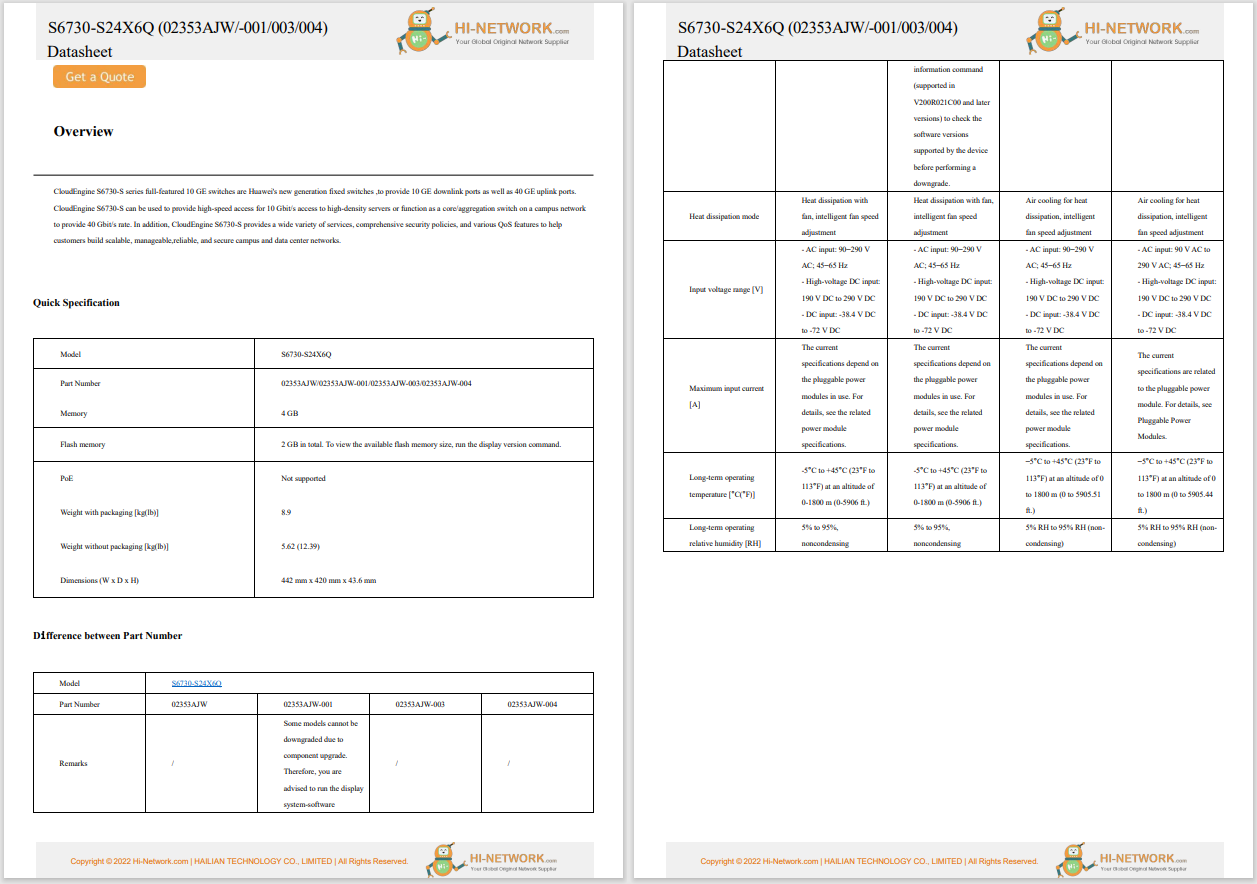
Figure 4-531 Indicators on the S5731-S48P4X (02353AJH)

Non. Non. | Indicator | Nom et prénom | La couleur | État d’avancement | Description |
|---|---|---|---|---|---|
1 | PWR1 | Indicateur de module de puissance | - | En dehors | Aucun module de puissance n’est disponible dans la fente de module de puissance 1, ou le commutateur a seulement un module de puissance mais le module de puissance ne fonctionne pas normalement. |
vert | Stable sur | Un module d’alimentation est installé dans la fente 1 du module d’alimentation et fonctionne normalement. | |||
jaune | Stable sur | L’interrupteur a deux modules d’alimentation installés. L’une des situations suivantes se produit dans la fente de module de puissance 1:
| |||
2 | PWR2 | Indicateur de module de puissance | - | En dehors | Aucun module de puissance n’est disponible dans la fente de module de puissance 2, ou le commutateur a seulement un module de puissance mais le module de puissance ne fonctionne pas normalement. |
vert | Stable sur | Un module de puissance est installé dans la fente de module de puissance 2 et fonctionne normalement. | |||
jaune | Stable sur | L’interrupteur a deux modules d’alimentation installés. L’une des situations suivantes se produit dans la fente de module de puissance 2:
| |||
3 | système | Indicateur d’état du système | - | En dehors | Le système ne fonctionne pas. |
vert | Clignotement rapide | Le système démarre. | |||
vert | Stable sur | Pendant la phase de préparation au démarrage du système, l’indicateur SYS est vert constant, ce qui dure au maximum 30 secondes. | |||
vert | Clignotement lent | Le système fonctionne normalement. | |||
rouge | Stable sur | Le système ne fonctionne pas normalement après l’enregistrement, ou une alarme de ventilateur ou une alarme de température a été générée. | |||
4 | MST | Indicateur de cheminée | - | En dehors |
|
vert | Stable sur | Le mode pile est sélectionné. Le commutateur est un commutateur de veille ou d’esclave dans une pile, et les indicateurs de port de service affichent l’id de pile du commutateur. | |||
vert | Clignant des yeux |
| |||
5 | vitesse | Indicateur de vitesse | - | En dehors | Le mode vitesse n’est pas sélectionné. |
vert | Stable sur | Le mode vitesse est sélectionné, et les indicateurs de port de service affichent la vitesse de chaque port. | |||
6 | PoE | Indicateur PoE | - | En dehors | Le mode PoE n’est pas sélectionné. |
vert | Stable sur | Le mode PoE est sélectionné et les indicateurs de port de service affichent l’état PoE de chaque port. | |||
7 | MODE | Bouton de commutation Mode | - | - |
Si vous n’appuyez pas sur le bouton MODE dans les 45 secondes, les indicateurs de port de service resteront en MODE par défaut. Dans ce cas, les indicateurs de vitesse et PoE sont éteints. |
Carte d’identité | Indicateur d’identification Remarque:The mode switch button on the 02353AJH has an ID indicator. | - | En dehors | L’indicateur ID n’est pas utilisé (état par défaut). | |
bleu | Stable sur | L’indicateur identifie le commutateur à entretenir. L’indicateur d’identification peut être allumé ou éteint à distance pour aider les ingénieurs de terrain à trouver l’interrupteur à entretenir. | |||
8 | - | Indicateur de port de service électrique (un indicateur pour chaque port) | L’indicateur dans le coin supérieur gauche d’un port indique l’indicateur d’un port en haut, et l’indicateur dans le coin supérieur droit indique l’indicateur d’un port en bas. | Meanings of service port indicators vary in different modes. For details, see Table 4-1350 and Table 4-1351. | |
Indicateur optique de port de service (deux indicateurs pour chaque port) | Chaque port optique a deux indicateurs de couleur unique. Celui de gauche est l’indicateur ACT (jaune), et celui de droite est l’indicateur LINK (vert). Les flèches indiquent les positions des ports. Une flèche de bas indique un orifice en bas, et une flèche de haut indique un orifice en haut. | ||||
9 | ETH | Indicateur de port ETH | - | En dehors | Le port ETH n’est pas connecté. |
vert | Stable sur | Le port ETH est connecté. | |||
vert | Clignant des yeux | Le port ETH envoie ou reçoit des données. | |||
10 | - | Indicateur de déploiement basé sur usb | - | En dehors |
|
vert | Stable sur | Un déploiement basé sur usb A été effectué. | |||
vert | Clignant des yeux | Le système lit les données à partir d’une clé USB. | |||
jaune | Stable sur | Le commutateur a copié tous les fichiers requis et terminé la vérification des fichiers. Le lecteur flash USB peut être retiré de l’interrupteur. | |||
rouge | Clignant des yeux | Une erreur s’est produite lorsque le système exécute le fichier de configuration ou lit les données du lecteur flash USB. | |||
Table 4-1350 Description of service port indicators in different modes (one indicator for each port)
Display Mode | La couleur | État d’avancement | Description |
|---|---|---|---|
Default mode | - | En dehors | Le port n’est pas connecté ou a été arrêté. |
vert | Stable sur | Une liaison A été établie sur le port. | |
vert | Clignant des yeux | Le port envoie ou reçoit des données. | |
MST stack mode | vert | En dehors | Port indicators do not show the stack ID of the switch. |
Stable sur | L’interrupteur n’est pas l’interrupteur principal dans une pile.
| ||
Clignant des yeux | The switch is the master switch in a stack.
| ||
Speed mode | - | En dehors | Le port n’est pas connecté ou a été arrêté. |
vert | Stable sur | 10M/100M/1000M port: The port is operating at 10 Mbit/s or 100 Mbit/s. | |
vert | Clignant des yeux | 10M/100M/1000M port: The port is operating at 1000 Mbit/s. | |
PoE mode | - | En dehors | The port is not providing power to a powered device (PD). |
vert | Stable sur | The port is providing power to a PD. | |
vert | Clignant des yeux | The power of the PD connected to the port exceeds the power capacity of the port or the power threshold configured on the port. Alternatively, the PD does not comply with IEEE standards. |
Table 4-1351 Description of service port indicators in different modes (two indicators for each port)
Display Mode | La couleur | État d’avancement | Description |
|---|---|---|---|
Default mode | - | En dehors | Le port n’est pas connecté ou a été arrêté. |
vert | Stable sur | Une liaison A été établie sur le port. | |
jaune | Clignant des yeux | Le port envoie ou reçoit des données. | |
Speed mode | - | En dehors | Le port n’est pas connecté ou a été arrêté. |
vert | Stable sur | 1000M/10GE port: The port is operating at 1000 Mbit/s. | |
vert | Clignant des yeux | 1000M/10GE port: The port is operating at 10 Gbit/s. 1000M port: The port is operating at 1000 Mbit/s. |
The switch is a PoE switch and supports two power module slots, each of which can have a 1000 W PoE or 600 W PoE power module installed. Pluggable AC and DC PoE power modules can be used together in the same switch.
Table 4-1352 Power supply configurations
Power Module 1 | Power Module 2 | Puissance disponible de PoE | Maximum Number of Ports (Fully Loaded) |
|---|---|---|---|
1000 W AC (220 V) 1000 W DC | - - - - - | 760 W |
|
1000 W AC (110 V) | - - - - - | 665 W |
|
1000 W AC (220 V) 1000 W DC | 1000 W AC (220 V) 1000 W DC | 1600 l |
|
1000 W AC (110 V) 1000 W DC | 1000 W AC (110 V) | Versions earlier than V200R021C10: 1330 W V200R021C10 and later versions: 1520 W |
|
600 W AC (220 V) | - - - - - | Longueur: 380 l |
|
600 W AC (110 V) | - - - - - | 95 l |
|
600 W AC (220 V) | 600 W AC (220 V) | 950 W |
|
600 W AC (110 V) | 600 W AC (110 V) | Longueur: 380 l |
|
1000 W AC (220 V) 1000 W DC | 600 W AC (220 V) | 1330 W |
|
When a switch has two power modules installed, the two power modules work in redundancy mode to provide power for the chassis and in load balancing mode to provide power for PDs.
The S5731-S48P4X uses pluggable fan modules for forced air cooling. Air flows in from the front side and exhausts from the rear panel.
This figure only shows the airflow direction and does not depict the actual device.
Table 4-1353 lists technical specifications of the S5731-S48P4X.
Table 4-1353 Technical specifications
Article: | Description |
|---|---|
Mémoire (RAM) | 1 GB |
Le Flash | 1 go au total. Pour afficher la taille de la mémoire flash disponible, exécutez the Afficher la versionRe88pl99ace1command. |
Temps moyen entre les défaillances (MTBF) | 54,96 ans |
disponibilité | > 0.99999-0.99999 |
Port de Service protection contre les surtensions | Mode commun: ±6 kV |
Protection contre les surtensions d’alimentation électrique |
|
Dimensions (H x l x p) |
|
Poids (avec emballage) | 8,8 kg (19,40 lb) |
Ports de pile | 10GE SFP+ ports sur le panneau avant |
Le CCF | Pris en charge |
RPS | Non pris en charge |
PoE | Pris en charge |
Gamme de tension évaluée |
|
Plage de tension maximale |
|
Consommation d’énergie maximale (100% de débit, pleine vitesse des ventilateurs) |
|
Consommation électrique typique (30% de la charge du trafic, testée selon la norme ATIS) | 110 l |
Température de fonctionnement | -5°C à +45°C (23°F à 113°F) à une altitude de 0 à 1800 m (0 à 5906 pieds)Remarque: Lorsque l’altitude est de 1800-5000 m (5906-16404 pi.), la température de fonctionnement la plus élevée diminue de 1°C (1,8 °F) chaque fois que l’altitude augmente de 220 m (722 pi.). L’interrupteur ne peut pas être démarrée lorsque la température ambiante est inférieure à 0°C (32°F). |
Température de stockage | -40°C à +70°C |
Bruit à température normale (27°C, puissance acoustique) | < 62,3 dB(A) |
Humidité Relative | 5% à 95%, sans condensation |
Altitude de fonctionnement | 0-5000 m (0-16404 pi.) |
Certification |
|
Numéro de pièce | 02353AJH 02353AJH-001 02353AJH-003 |
 Tags chauds:
Interrupteurs Huawei
hot products
datasheet
Tags chauds:
Interrupteurs Huawei
hot products
datasheet
Inscrivez-vous par courriel maintenant pour le Stock de Promotion hebdomadaire
100% free, Unsubscribe any time!
Add 1: Room 605 6/F FA YUEN Commercial Building, 75-77 FA YUEN Street, Mongkok KL, HongKong Add 2: Room 405, Building E, MeiDu Building, Gong Shu District, Hangzhou City, Zhejiang Province, China
Whatsapp/Tel: +8618057156223 Tél. : + 33 (0) 3 88 88 20: 0086 571 86729517 Tel à HK: 00852 66181601
Courriel:: [email protected]
 English
 Pусский
 Français
 Español
 Português